 Old oem Celica rear speaker next to a new Polk audio DB5252 speaker
Intro
So you bought yourself an ST205 and want to upgrade the sound system to the 21st century? Well you are in luck as the process is very straightforward and hopefully with this article you will be able be ready for the roadblocks that i’ve run into. Although straightforward, expect this to take a bit of time to fully complete. If you have all the parts and tools beforehand, a solid weekend of tinkering should be all you need.
This article is not a complete guide and will assume you are capable of removing panels, soldering connections, crafting mounts, etc. This is also my first article on the site so formatting and flow will probably be wonky.
Equipment Used
This is the equipment I used for on this project, feel free to swap whatever with your preferred brands.
Audio/Nav System
Tools / Hardware
|
|
Interior Removal
So the first step to start this process is the removal of all the interior trim and rear seats to get access to the OEM speakers. Compared to other JDM cars I have worked with (just a Subaru GC8) this Celica has been simpler in my opinion.
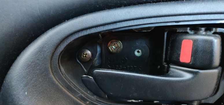
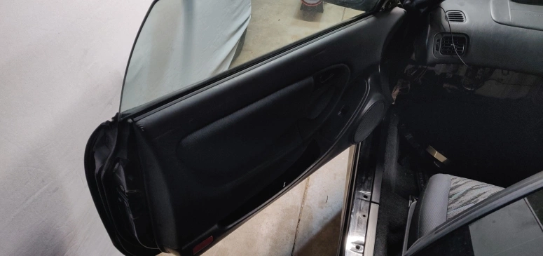
The door cards/panels were straightforward. They both had two/tree plastic plugs that had screws underneath, so just pop the plugs with your plastic trim tools and undo the screws. There was also a hidden screw under the inner door handle plastic cup as seen here:
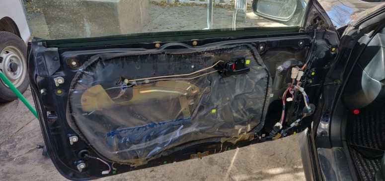
Then once you remove all these screws and plastic retainers, with a little bit of wiggling you can pop out the door panels/cards and disconnect the power window switch and illumination light cable from them.
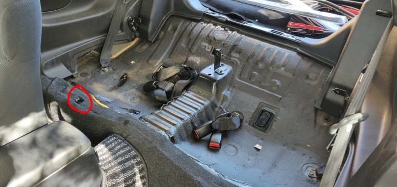
After this you can start the removal of the rear seats and the rear side trim (the trim that contains the rear speakers). The rear speaker grilles can be popped off with a trim tool to reveal additional screws to remove. The only small tricky part I recall is the bottom portion of the rear seat. Once you unbolt everything from the seat, you have to yank the front part of the cushion to remove it from the car frame. It is connected by two metal hooks that lock into the “lock hook” mechanism. The red circle on the image shows where these hooks go into and where you have to pull from to remove the rear seat cushion.
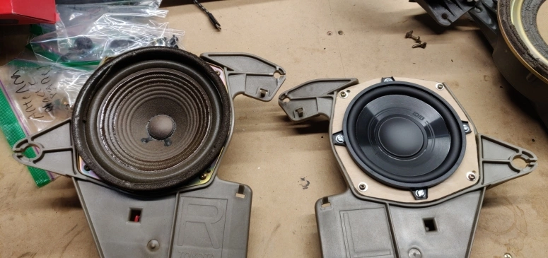
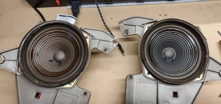
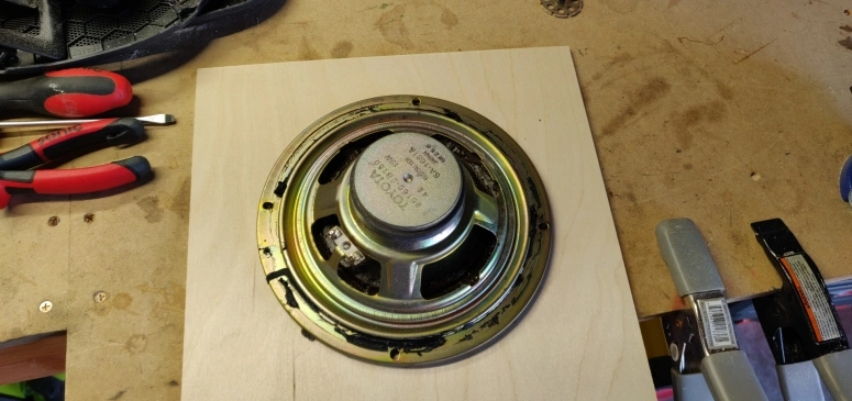
Once you are done removing all the necessary trim you can now unplug and unscrew both the front and rear speakers. Since your Celica is probably over 25 years old they will prob look a little bit like this:
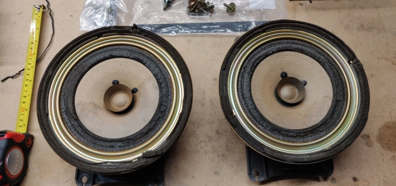
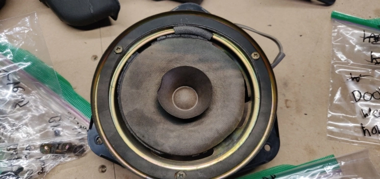
The front speaker diaphragms were a bit petrified and the foam was starting to fall apart. The rears faired a bit better, but still in a poor state. I’m not too knowledgeable when it comes to speaker technology, but to me this is one of the downsides to using paper as a woofer material. Humid conditions, like the ones found in Japan, lead to a deterioration in the speakers over time. Now granted this is over 25+ years, but i’m sure if polypropylene cones were used back then (if the technology existed in the 90’s not sure) the old oem speakers would have held off much better. Paper technology and chemical coatings have probably come a long way since then, but i’m still hesitant to use or recommend paper speaker woofers because of this. These were not so bad compared to the ones found on my 1994 WRX STi:
Regardless, with this mini rant out of the way lets move on to the next section.
Installing the new speakers
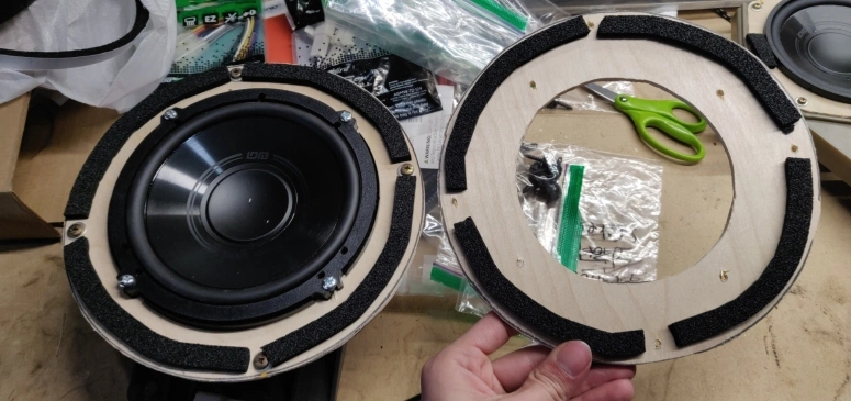
Take the new speakers you ordered, remove them from their packaging, and then come to the realization that they do not fit properly and the included speaker adapters won’t work either. Unfortunately I ran into this issue when my small brain blindly trusted Crutchfield that a 6.5" speaker will work in the front and a 5.25" speaker will work in the back.
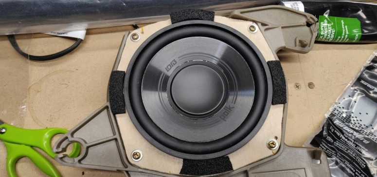
Now on the Mr. Brightside I wanted to use the Polk Audio DB speakers regardless as they are well reviewed. I have also used them before on my 94 STi and liked the sound quality they produce. Here are the new speakers in comparison to the Celica speaker brackets:
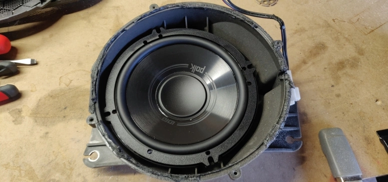
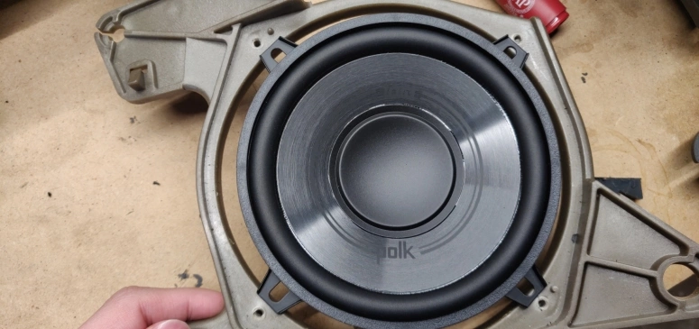
As you can see the mounting screws do not line up properly on either bracket. The front speaker brackets have a screw spacing of 8" and the rear speaker bracket has a screw spacing of 6.25". I can’t recall exactly, but I kinda remember trying the 6.25" DB6502 speaker in the rear and it STILL did not line up properly. Looking online I found some threads stating certain 8" speakers worked like the Focal ISU 200 on the front bracket without any modifications, but chances are the speakers you prefer or want to buy will require some modification and crafting.
Hopefully you are better equipped than me, but all the following custom speaker adapters were done with just a Dremel 4000-6/50. The adapters a little sloppy around the edges, but It did not turn out too bad.
Rear speakers
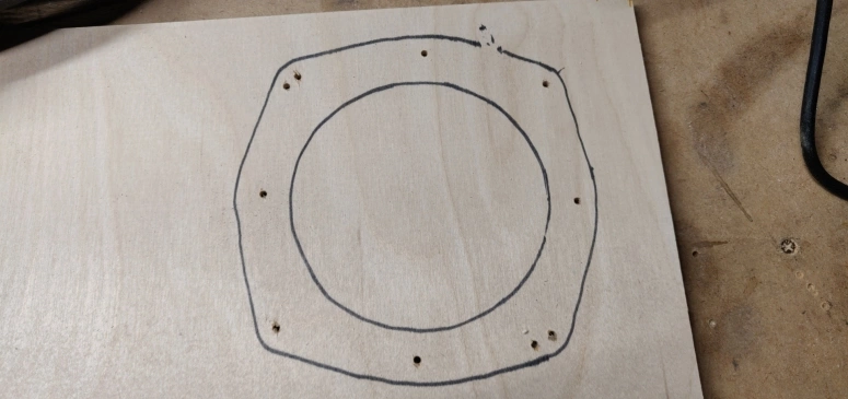
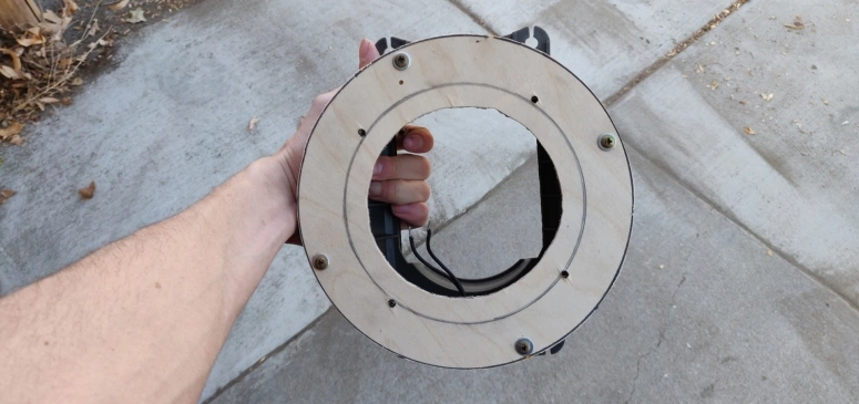
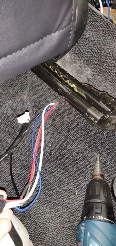
I first started by removing the old speakers from the bracket (you will need to desolder the wire connections as they hardwired/soldered on). Then I flipped the speaker over a birch plywood I bought from Home Depot and drew a rough outline of the adapter frame the old speaker had. In the middle of the outline I then drew a circle slightly smaller than the DB5252 speaker to allow the speaker edge to rest on the plywood and not fall through.
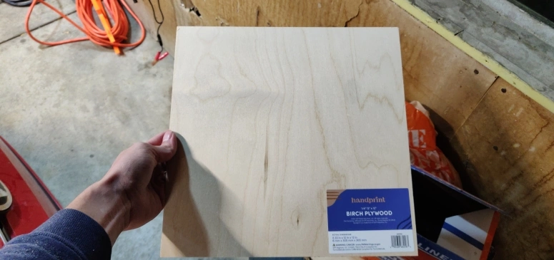
This is the birch plywood squares I bought from Home Depot:
With the aftermath of a lot sawdust everywhere, I drilled out the outlines with the Dremel:
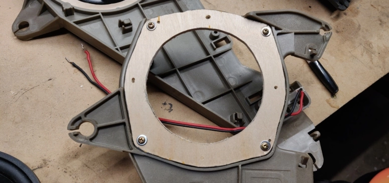
And was able to secure the speaker with cheap nuts and bolts I have bought from Harbor Freight:
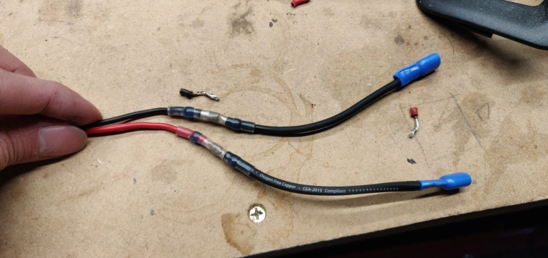
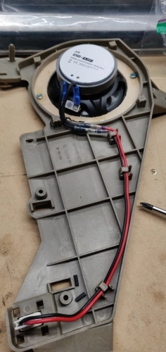
I would suggest to add a bit of blue loctite 242 (or equivalent) on the speaker bolts to prevent the nuts from shaking loose. Also add a bit of foam tape on the edges as seen on the picture above to prevent any rattling against the speaker grille. As far as the wiring in concerned, extend the existing cables you desoldered with 16 gauge speaker wire using the Kuject butt connectors to connect them. Then add spade connectors from the Nilight Quick Disconnect Terminals kit. The results will look something like so:
In the end I went through a few birch plywoods before I finally cut one that was half way decent. If you do not have better equipment or have the same mediocre woodwork skills as me, making these brackets will take a bit of time. If possible might I suggest trying to create these brackets out of an acrylic sheet rather than birch wood for increased durability and humidity resistance.
Front Speakers
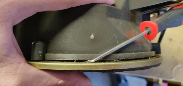
The front speaker adapters are much easier to cut out than the rears. The rears had this rounded square shape going on which made routing the outlines free handed with only a Dremel way too annoying. The front adapters are just a 8" diameter circle with another circle in the middle to let the front speakers rest on it. So unless you are buying an 8" speaker that will avoid all this your first step will be to remove the sticky sealant from the speaker and the frame.
After you pry the speaker off and desolder the wires, flip that speaker over on top your wood panel and trace the speaker outline as well as the screw holes.
Once everything is fully cut mount the adapter back to the front speaker bracket using some 3M Weatherstrip adhesive to replace some of the adhesive you peeled off. Then install the new speaker and add some foam tape to the edges of the adapter to prevent any rattling sounds on the door panel. Remember to add blue loctite 242 on the speaker nut and bolts.
Now all you have to do is add some spade connectors to the wires you desoldered and attach them to the speaker terminals.
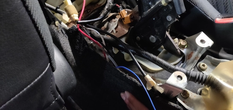
Center Console Trim Removal
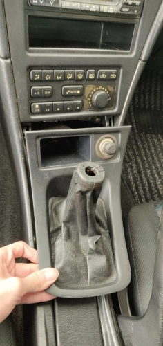
Before moving on to the head unit, you will need to remove all the center console trim pieces to get access to the old cassette deck unit (or whatever came your Celica). Start off by removing the shift knob and then popping off the shift boot/cigarette lighter trim with your trim pry tools (don’t forget to unplug the cigarette lighter wire before yanking it off).
With this removed it will expose two screws which I have circled in red on the next image. Remove these screws and once again pop off the head unit trim with your trim tool.
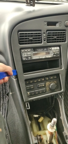
Carefully disconnect the top two connectors from this trim and set it aside. All you have left is to remove the actual head unit cage and disconnect the wiring harness from the cassette deck.
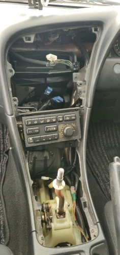
The two blue connectors you see in the image is the Celica’s wiring harness. These will be diagramed and explained in the next section.
Head Unit Connections
Luckily the JDM version of the Celica did not cause any additional difficulty when connecting the head unit wire connector to the receiver wiring harness. It did, however, make me spend a lot of time cross referencing multiple sites including the Crutchfield “WireGuide™” to make sure everything lined up correctly. The following is an aggregation of all the information I have rounded up.
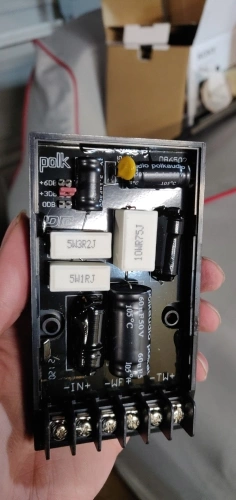
So first of all the head unit I went with is the Sony XAV-AX7000. The big reason I went with this unit is that this specific model comes with a built-in amplifier. This means I don’t have to mess around with trying to find a spot to mount an external amplifier which would take up the little amount of cargo room the Celica has. The built in amp has a 45 watt RMS and a 100 watts peak which lines up well with the Polk Audio speakers. The Polk Audio speakers also have a very high db sensitivity (91/92 db) which will allow the Sony XAV-AX7000 to easily drive them.
The receiver wiring harness I got (which came for free with my Crutchfield order) is the Metra 70-1761 Receiver Wiring Harness. This is what the head unit will connect to and then in turn connect to the Celica’s wire harness.
Here is the Celica’s wire harness connectors with a diagram of the wire factory colors that are attached to said connectors.
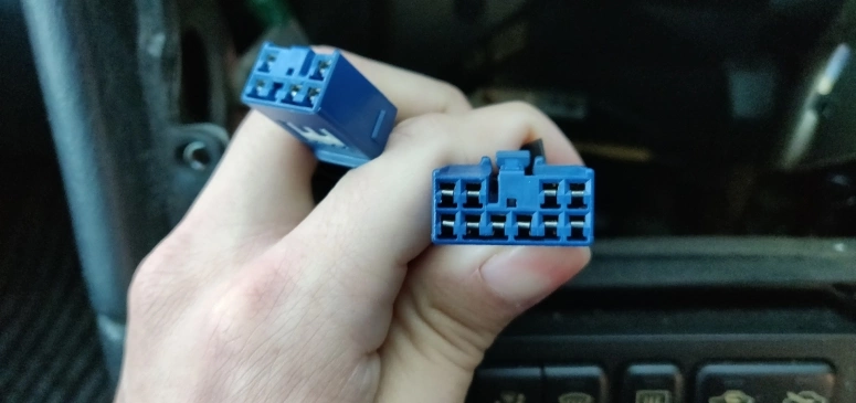

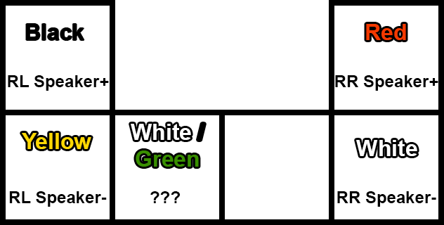
Note that these colors DO NOT MATCH the Metra 70-1761 Receiver Wiring Harness nor the Sony XAV-AX7000 unit wires. I’m assuming the wire color scheme used in the ST205 was an old obsolete scheme or maybe just a random scheme, not entirely sure.
Now here are the actual connections you will need to make. I’ve also added connections for the Kicker powered sub, the backup camera, and the parking override bypass.
| Sony XAV-AX7000 16-Pin Black Connector | Metra 70-1761 Wiring Harness 10-Pin Connector | ST205 | MicroBypass | Kicker 46HS10 | Nakita Reverse Cam | |
|---|---|---|---|---|---|---|
| ACC | Red | Red | Red | |||
| Front Left Speaker + | White | White | ||||
| Front Left Speaker - | White/Black | White/Black | ||||
| Front Right Speaker + | Gray | Gray | ||||
| Front Right Speaker - | Gray/Black | Gray/Black | ||||
| Illumination | Orange/White | Orange/White | ||||
| Remote / Antenna / Amp Turn On | Blue/White | Blue | Blue | Blue | ||
| Constant Power | Yellow | Battery Positive Terminal | Red | |||
| Parking | Light Green | Green | ||||
| Ground | Black | Bare metal | Black | |||
| Ground | Black | Black | Black |
| Sony XAV-AX7000 16-Pin Black Connector | Metra 70-1761 Wiring Harness 6-Pin Connector | |
|---|---|---|
| Rear Left Speaker + | Green | Green |
| Rear Left Speaker - | Green/Black | Green/Black |
| Rear Right Speaker + | Purple | Purple |
| Rear Right Speaker - | Purple/Black | Purple/Black |
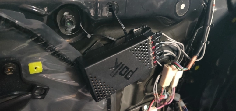
To clear a little confusion on the first table, both the Sony XAV-AX7000 and the Kicker 46HS10 were grounded to the chassis. Using a ring terminal the Sony head unit was grounded to a nut/bolt behind the center console and the Kicker sub to the a nut/bolt on the driveshaft tunnel. Also the constant power from both the head-unit and powered sub were routed through the firewall and to the positive battery terminal, more on this in a later section.
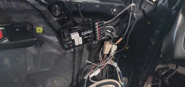
For the the connections from the Sony XAV-AX7000 to the Metra wiring harness that were 1:1 the Kuject butt connectors were used. All other connections I used WAGO 221 LEVER-NUTS. The personal reason for this was to have the flexibility to add or remove cables from these “non-permanent” connections without worrying about having to cut and resolder the wires. This will be convenient in the event if a new electrical device gets added or removed.
All the remaining wires that were not used were taped off such as the Metra’s yellow constant or the Sony XAV-AX7000’s brown and green input wires.
Subwoofer
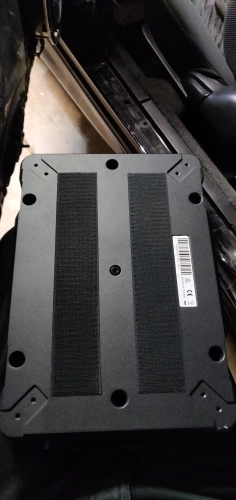
So the subwoofer I went with is the Kicker 46HS10 which is a compact self powered 10" sub. For the same reason I got the Sony XAV-AX7000, I went with a self powered sub to save as much space as possible. I could not afford to use up any trunk space to put in a boxed sub.
The best place I found to install this sub was under the passenger seat. With the addition of a few washers for the rear left seat bolt, the seat is able to slide back and forth without hitting the Kicker 46HS10.
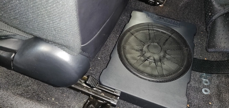
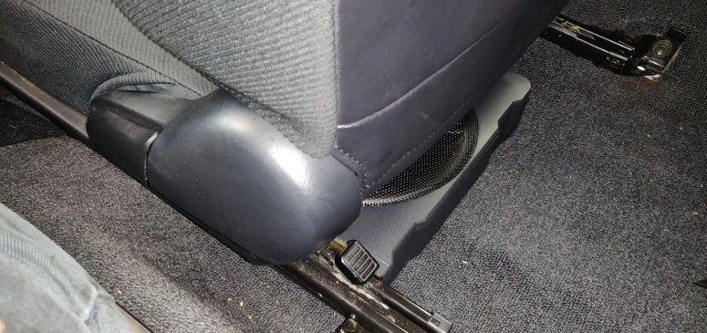
However the grille on the Kicker 46HS10 does come in contact with the seat if there is someone sitting on it. The washers did help a bit, but to my knowledge there are only 3 options one can do to alleviate this or fix it completely.
- Buy the smaller 8" Kicker Hideaway HS8
- It is 3-1/4" height vs 3-3/8"
- Hammer in the grille on the Kicker 46HS10
- The grille sticks out unnecessarily compared to the frame and can be hammered flat without sacrificing sound
- Lift the actual passenger seat
- This is a lot of work. I used some washers on the rear left bolt which aided a bit in raising the seat, but the rear right bolt on the passenger seat is bolted on the side of the driveshaft tunnel. So adding washers there would not accomplish anything. Some custom fabrication will be required.
The option that I went with is option #4, none of the above. Having someone in the seat did not affect the bass in any way nor create any unwanted rattle. However, if this grows to be a concern in the future I will probably go with option #2 as it’s the easiest.
To conceal the wire connections, cutting a hole in the carpet near the bottom of the driveshaft tunnel proved to be quite good:
Make sure to cut this hole near the area where the connector on the Kicker 46HS10 will be to avoid any cable bending. The cables can then be ran up the driveshaft tunnel and up to the head unit location without any pinching.
Connecting the Kicker 46HS10 to the Sony XAV-AX7000 was really easy with the purchase of the Kicker 46KISL 2ch. Speaker-RCA Converter and the AudioQuest RCA adapter. Just use some butt connectors to connect the subwoofer harnesses audio wires to the Kicker 46KISL RCA converter. Next attach the AudioQuest RCA adapter and connect it to the sub-out port on the Sony XAV-AX7000. Since the subwoofer harness and the RCA adapter are both from Kicker the wire color scheme connections are really easy:
| Kicker 46HS10 | Kicker 46KISL | |
|---|---|---|
| Left Channel Positive | White | White |
| Left Channel Negative | White/Black | White/Black |
| Right Channel Positive | Grey | Grey |
| Right Channel Negative | Grey/Black | Grey/Black |
Mounting the subwoofer is also really easy. The Kicker 46HS10 does come with a few mounting brackets inside, but there was no real way to attach it to anything under the passenger seat. What I ended up doing is attaching two really long strips of double sided velcro to the back of the unit, but just using the side with the hooks so it can sink in and grab unto the carpet.
Once the velcro strips grab unto the carpet it is not going anywhere. Keep in mind that removing this is a real pain in the butt unless you remove the passenger seat (learn from my dumb mistake). Save this step for the very end once everything else is done.
Constant Battery Terminal Power
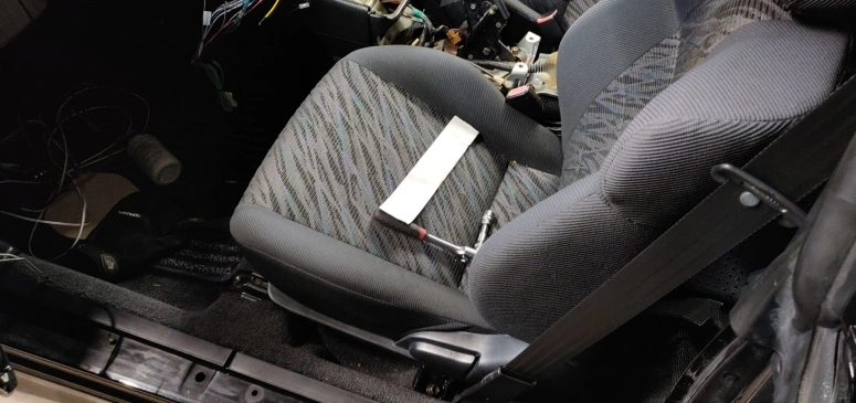
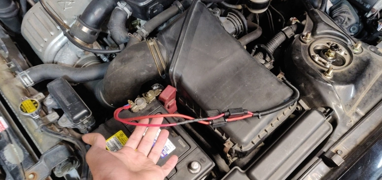
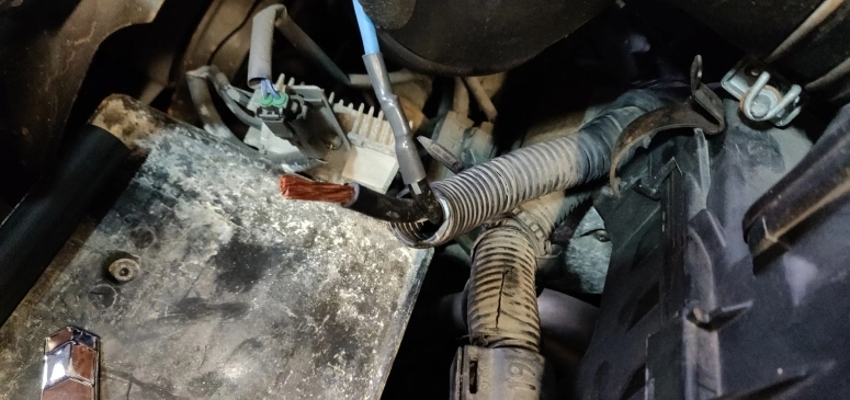
Both the Kicker 46HS10 and the Sony XAV-AX7000 are required/recommended to be connected directly to the car’s positive battery terminal. This means you will have to run cables through the car’s firewall. Luckily the ST205 has a convenient grommet you can go through on the passenger side. Located on the rear right side of the engine bay (looking at it) remove the two nuts holding the grommet. If you run into the issue like I did where the grommet was seized on, just use some elbow grease and maybe a bit of penetrating fluid to yank off.
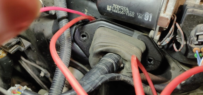
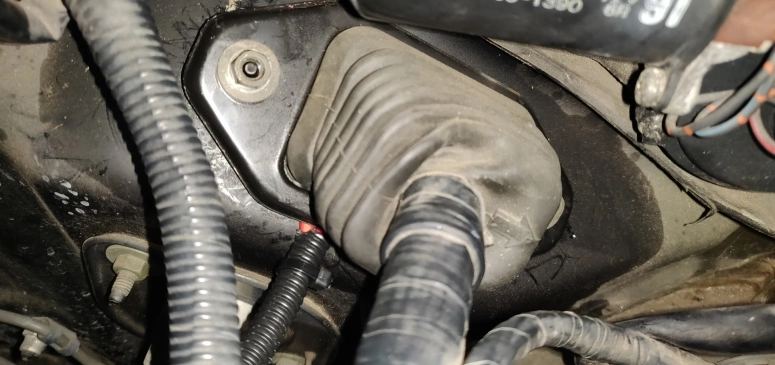
In the image above you can see I decided to run the power cables to the head unit and subwoofer underneath the grommet itself. You could slit a hole through the rubber grommet and run it directly through, but It’s a bit of work to make it look sleek and OEM (in my opinion). I did however make sure that placing the grommet back on top of the cables won’t pinch them. As for the cables themselves, the Kicker 46HS10 already came with wiring to connect to the battery and for the Sony XAV-AX7000 I went with the Crutchfield CK12 wiring kit. After you run the cables through the grommet opening and cut it to the proper length, just connect it to the positive battery terminal and neatly apply some cable management to the cables to avoid any interference. You could also decide, like I did, to extend the Crutchfield CK12 lead to be able to hide the fuse on the right side the battery.
While this is properly and safely connected, I didn’t like the look of these cables connecting to the battery terminal this way. I also have plans on adding fog lights which means I will have yet another cable to connect to the terminal. This is where the T-SPEC - Battery Terminal comes in. This terminal allows for 4 cable connections to be neatly attached to the battery terminal. To get this installed just cut the existing terminal connector off of the starter and harness wire (I think this is what these are). Make sure to cut as little as possible as it will be a real pain to run new wires if cut too short.
Once cut we now need to extend them to be able to reach the battery terminal once again. I cut off my desired length of cable from the THIKPO G420 Jumper Cables I purchased and attached it to the starter cable (the thicker one) using the Gardner Bender HSB-28 to make the connection.
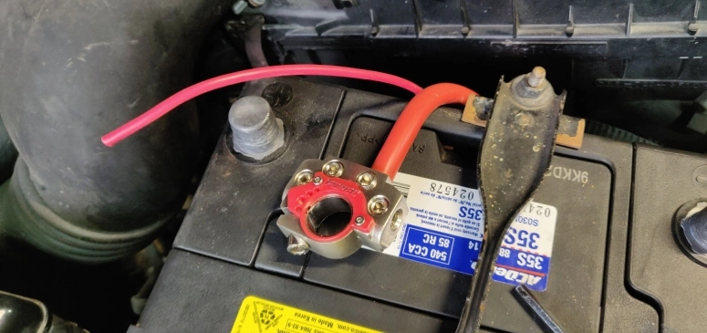
I then cut off the ring terminals from the subwoofer power cable and the Crutchfield CK12 wiring kit and attached them to the T-SPEC connector.
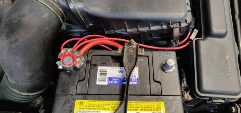
As you can see I left a spot open for my future fog lights and connected both the subwoofer and head unit power cables to the same connector on the T-SPEC terminal. One thing to note about this T-SPEC terminal is that it did not properly fit on the battery terminal node. I had to actually pry it open a bit and find a longer bolt to be able to secure it in properly. This might vary from battery to battery, but it is something to keep in mind.
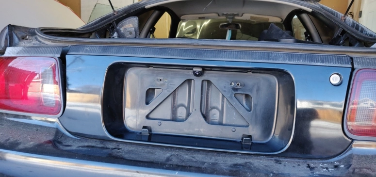
Reverse Camera
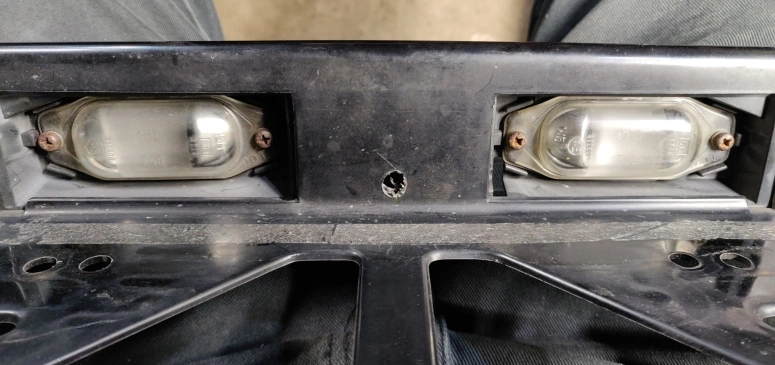
The rear view camera I opted for was the NATIKA Backup/Front View Camera. It is well reviewed and has decent picture quality for a pretty cheap camera. Unless you have a very specific reason, there is no need to get an expensive camera or anything with crazy high resolution since the main purpose of a back-up camera is to tell you if you are going to hit something or not. The place I settled to install the camera is the rear center panel. To get this panel off you will need to first remove all trunk trim panels. These are very straightforward and if you already removed the rear seats in the previous steps you will have easy access to the screws and plastic trim clips. You don’t have to fully remove the panels, just enough to have space to work in. Once you are done with the panels the next step is to remove the rear tail lights. The rear tail lights are held in by three nuts as show below:
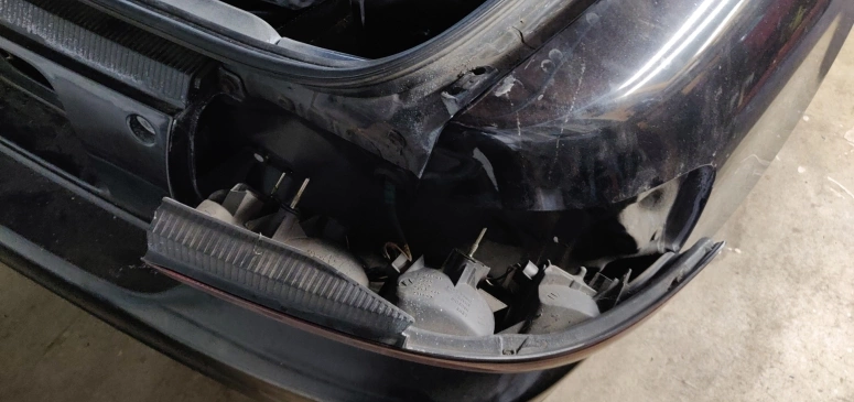
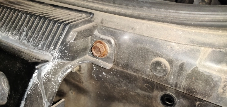
My 1996 ST205 did not have any weather adhesive holding the rear taillights unlike my 1994 STi (might be the same with all other ST205s). So with a little wiggling they were able to come off easily. Once the taillights are removed you will then see these two nuts (mine were pretty rusty) on either side of the rear center panel:
Remove those two bolts and now the only thing holding the center panel in place are 8 plastic retainers as seen here:
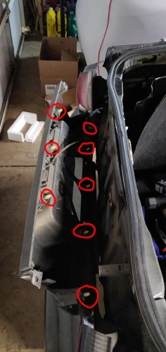
The best way I found to remove these was spray a little bit of penetrating fluid on the retainers themselves and using a rubber mallet to carefully hammer the retainers out from the trunk. Once you popped out all the retainers, unplug the rear license plate light cable and you are done.
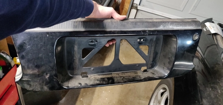
Next step is to drill a hole in the panel for the backup camera (The NATIKA instructions recommended a 5/16" drill bit I believe). The drilling location I settled for was the top of the panel above the license plate mounts:
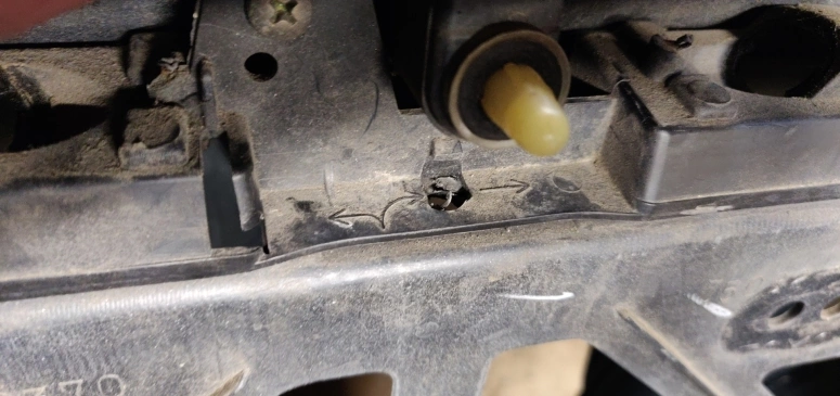
To drill this hole I had to remove the bracket that held in the license plate lights. I then placed the rear camera on to make sure everything aligned well and was flush.
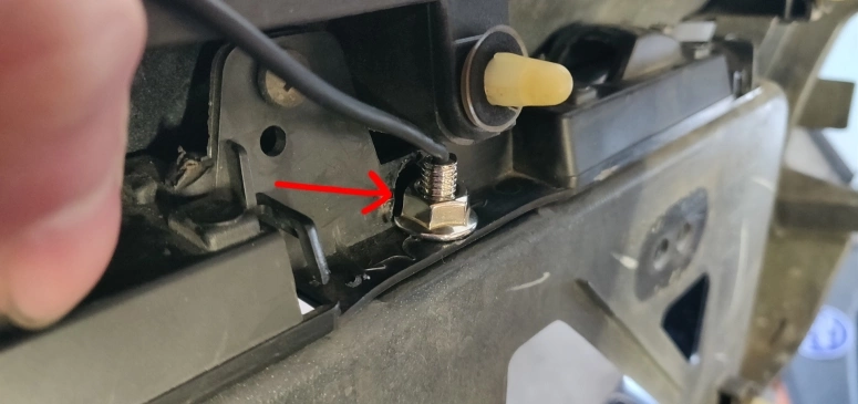
Once everything looks good, the last thing you will need to do is cut a hole on the license plate light bracket to allow the nut for the camera to spin freely and secure the camera on. Here is a picture with a red arrow showing what I did on the light bracket:
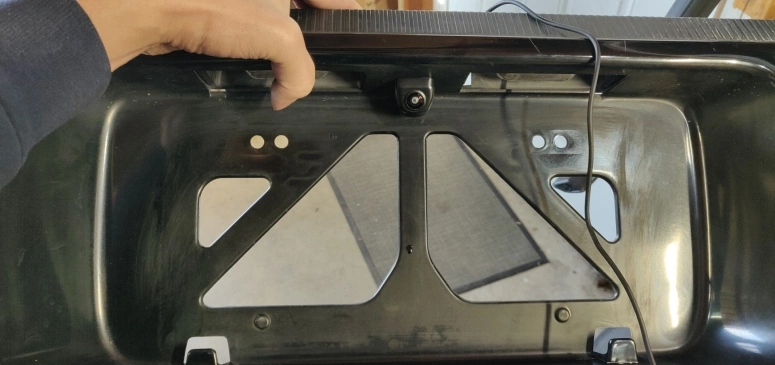
After you secure the rear camera on you then need to run the camera wire into the trunk. I decided to use the existing grommet for the license plate lights cable. A more professional option would have been to drill a new hole for it, but this was works well enough. Now all that is left is to install everything in reverse order and with a bit of cleaning the final result will look pretty good:
Now run the camera wires all the way back to the center console to plug into the head unit. I decided to run the wires on the passenger side and through a channel in the passenger door sill:
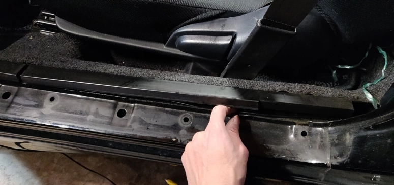
With all the interior trim removed from the speaker installation this should be very easy. Just take your time and do some proper cable management. Also keep in mind that the NATIKA back-up camera comes with built in guide lines with the option to remove them by cutting certain wires on the camera (read the instructions). I would recommend to not cut them yet and wait till everything is attached to the head unit for you to decide if you prefer the built in guide lines or use the ones on the Sony XAV-AX7000. I opted for the built in NAKITA guide lines and turned off the Sony guide lines in the head unit settings.
Reverse Camera Indicator
So the Sony XAV-AX7000 has a feature (along with probably all other modern head units) that switches to the reverse camera automatically when the car is put into the reverse gear. This is the purple/white wire on the Sony XAV-AX7000. Unfortunately the ST205 (at least for the 1996 model) does not feature a reverse indicator on the main wire harness. This means you will have to do some hunting on where to connect the purple/white wire to. There are two options you can do when it comes to the ST205.
- Connect to the back-up light switch (Either the IL1 or IG1 connector)
- Connect directly to the reverse tail light switch
Here is the diagram of the back-up switch:
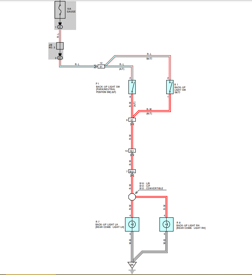
The IL1 connector is located in the engine near the engine control module:
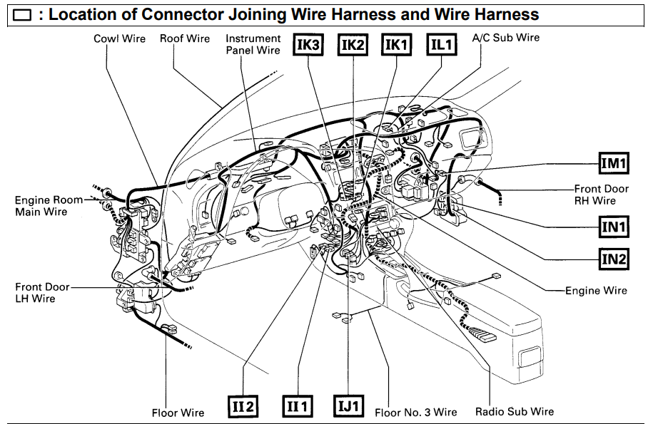
The IG1 is located in the kick panel:
I initially opted for the first option, but unfortunately I could not find the IG1 connection at all. The diagrams I provided were all I had to go off of and the diagram itself is reversed (it shows a left hand drive car). I think the IG1 is actually on the driver side somewhere, but i’m not 100% sure. I could have traced the rear tail-light wire to the BQ1 connector (which is located on the right rear side near the suspension pillar) all the way to the IG1 connector, but even if I did find it there would have been hardly any room to work in. This would have been very annoying trying to splice a wire down there so instead I went with option #2.
Option #2 is the easiest and what I would recommend. If you already took off the trim and lights trying to install the reverse camera, this will be incredibly easy.
First find the connector for the rear tail light. I choose to the rear-left light as I was already running the reverse camera through the passenger side. Once you found the connector, unplug it and find the red/white wire on it. This is the power to the back-up bulb (might not hurt to double check this with a buddy and a multi meter).
After you find the correct wire, cut it and attach a 3 conductor WAGO 221 lever nut to it. Two ports to restore the original connection and the third port to run a wire from to the head unit.
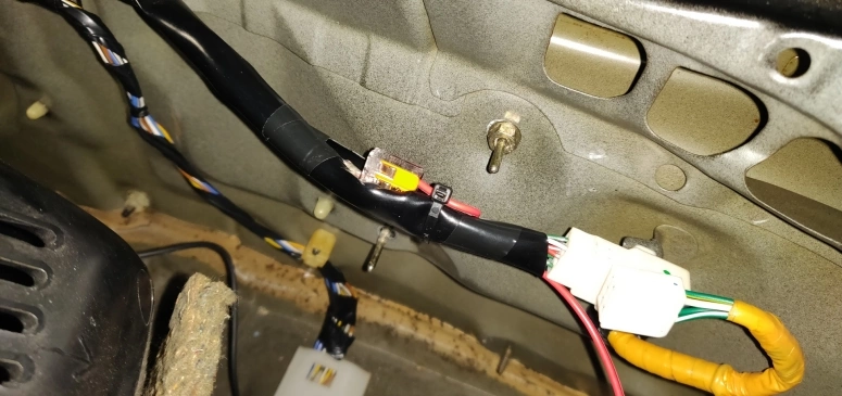
The wire I used to attach to the Wago 221 lever nut and run to the head unit was a 18 gauge TYUMEN 40FT 2 Pin wire. I simply cut it to length and removed the black wire to make it a single wire going back to the center console.
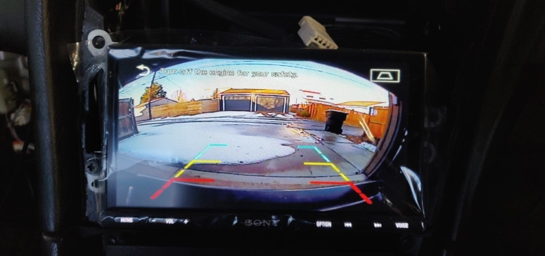
If everything is connected properly, the head unit will now automatically switch to rear camera once the reverse gear is engaged:
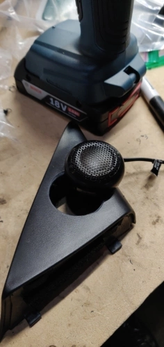
Optional Tweeters
I am not fully certain, but it seems tweeters were a dealer upgrade back in the 90’s for the ST205. If you look around the web, the side mirror trim pieces either have a tweeter frame built in to it or are just flat. The ones in my ST205 were flat (part number 6749120320 and 6749220320) did not come with factory tweeters. However, there seems to be a connector for them on the door frame right next to the main door speaker. Just some random information.
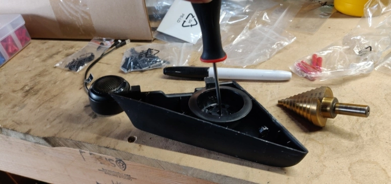
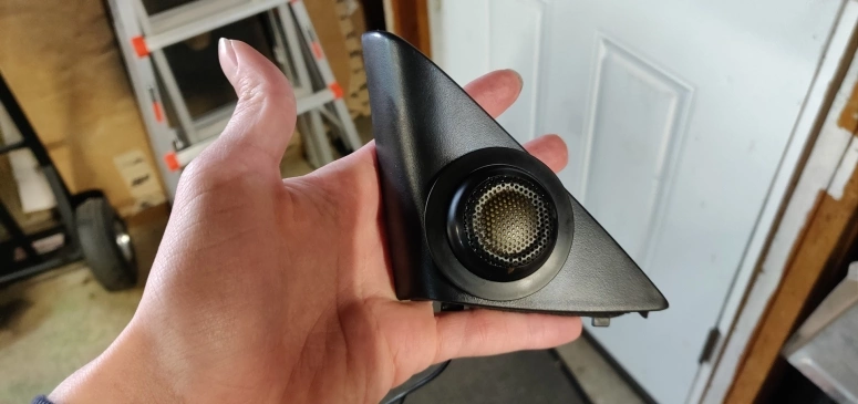
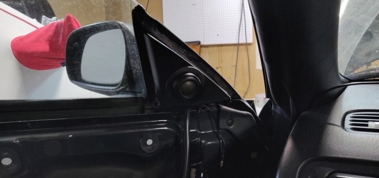
The Polk Audio DB 6502 speakers came with two tweeters and a passive crossover to hook everything into. The Polk Audio DB 5252 also came with the same tweeter and crossover setup, but two is all you really need. Since I wanted crispy highs on my audio I opted to custom install the tweeters in the front side mirror trim pieces.
The first thing I needed was the ZELCAN Large Step Drill Bit. This had the perfect hole size to allow the tweeter housing to pass through. Just center the housing, punch a pilot hole through, and then drill to the appropriate size.
Once you finished both side mirrors the next step is to find a place to install the passive crossover without it interfering anything. The best place I found was near the upper door frame here:
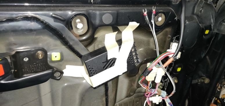
I put on the door panel to make sure I was able to install it later without having to bend or break something. Once I knew this location would work I secured the crossover housing with double sided velcro adhesive and cable ties. There is most likely a better way to install this crossover, but this is the best my noggin and lack of tools can come up with. Now all you need to do is extend the speaker wires so they can reach the crossover mounted location.
- The speaker connector on the doors needs to be cut off and extended
- The main signal wire from the harness (that was cut off from the connector) needs to be extended to reach the crossover
- The tweeter wire needs to be extended
This is a total of 6 wires that will need to be extended. I used the spare speaker wire that came in the Polk Audio DB 6502 package for all these extensions.
If you secured the Polk Audio crossover using my cable tie method you will run into the issue where the crossover cover does not sit properly due to the cable tie being in the way. To resolve this I simply filled a groove on the housing where the cable tie is and was able to put on the cover on no problem.
If you are wondering what decibel I set the tweeters to the answer is 3db. 6db is what came by default and was a bit too loud for my taste. I actually didn’t know the crossover had a tweeter decibel setting until I removed the cover to do the custom mounting. The decibel selection is in the upper left corner of the housing.
Head Unit USB Port
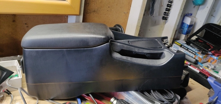
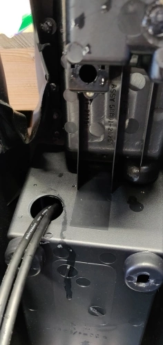
So the Sony XAV-AX7000 comes with two USB type a female connector cables which are used for wired Android Auto/Apple Carplay and media playback. To hide these cables and make it look official/OEM, I decided to install a 2 Port Dual USB 3.0 mount. The best place I found to install this was inside the center console box. With the shift boot out of the way from the previous step, unbolt the center console box and remove it from the car.
Next take the step drill bit and drill a hole for the USB mount. The place I opted for was near the bottom of the center console box storage compartment:
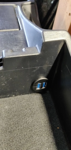
Now simply re-install the center console box and route up the USB wires to the head unit. The placement is a bit awkward to connect a USB cable to, but if you leave a USB cable connected to it all the time it’s not really a big deal. Plus I personally don’t use phone navigation much unless i’m going on a long road trip which means 99% of the time I will be connected to bluetooth anyway.
Summary
Hopefully this article will be useful to someone. A lot of vehicle information is shared for free online on various different sites that I just wanted to give back to the community. All the photos on this article have been resized for web optimization. If you want to see higher resolution images as well as images of the project that I didn’t upload here, a Google photos album has been created.
Looking back on this audio upgrade, the only thing I would change is the speaker adapters for the speaker brackets. I would have rather have made them with acrylic rather than wood. Luckily I live in a dry climate, but I will still be checking on them every once in a while to see how they are holding up. I also recorded my progress towards the end of the project. Mostly just to remind myself where and how I ran the wires. Here is the link to that video: https://youtu.be/0D09l8Cgm2k. Could be useful into seeing how I ran all the wires and were I grounded stuff to.
If you have any questions just leave a message below (if Disqus works) and I’ll try to answer them.